TWO MONTHS
INDUSTRIAL TRAINING REPORT
Held at
ENGINEERING TECHNOLOGY SOLUTIONS(ETS)
KURUKSHETRA (HRY.)
Submitted
in partial fulfilment of the requirement for the 6th Semester
Curriculum Degree of Bachelor of
Technology in
“INSTITUTE OF INSTRUMENTATION ENGINEERING”
Of
Kurukshetra University,
Kurukshetra

DEPARTMENT OF INSTRUMENTATION ENGINEERING
INSTITUTE OF INSTRUMENTATION ENGINEERING, KURUKSHETR UNIVERSITY
, KURUKSHETRA
SUBMITTED
BY:-
contents
·
certificate
·
acknowledgement
·
objectivE of
training
COMPANY profile
·
INTRODUCTION
·
OBJECTIVES
programmable
logic controllers
·
PLC
BASICS
·
HISTORY
·
OLD WAYS
·
IT IS NOT HARD TO IMAGINE
·
EARLIER
·
Need for PLC
·
Advantages of PLC
·
AUTOMATION
· What is a PLC?
·
GUTES INSIDE
·
PLC OPRATION
· PLC Basic COMPONENTS
·
About Inputs and Outputs of PLC
·
ANOLOG VERSUS DIGITAL INPUTS & OUTPUTS
·
HOW PLC REMOVING COMPLEXITY?
·
RELAY
·
REPLACING RELAY
·
WHAT IS CONTROL PROGRAM?
·
PLC Architecture
·
About Ladder Logic
·CONTACTS
· INDUSTRIAL SENSOR
ACKNOWLEDGEMENT
I have reached to this opportunity to thank all those who
have been guide me on interval of my training & this report to completion.
I am also grateful to Sh., Director of ETS.
I am grateful to all staff members of
ETS
for this remarkable and outstanding cooperation.
They help me and guide me for right
path of training.
I am also very thankful to my friends
who contributed a lot in solving the problems & devoted their valuable time
in spite of their own studies.
I take this opportunity to bring on
record the inspiration, help and indulgence.
OBJECTIVES OF TRAINING
·
The
main objective of training is to get first hand technical and practical
knowledge of PLC
The main purpose is that
the students would become familiar with industrial environment so that they can
take up future challenges when they turn up in an industry with good
confidence.
·
The
students will thus understand the flow of control and information in an
industry.
·
This
eight weeks training has been introduced in degree Engg. Courses for the
enhancement of students’ administrative and professional knowledge about their
respective fields.
·
After
completion of their degree courses this training experience will help them to
make their workplace stronger in the ever-competitive job fields.
COMPANY PROFILE

INTRODUCTION
ETS has grown to be a company with the
potential to become the strategic partners for world-wide customers for their
software needs for Semiconductors & Embedded.
ETS has a passionate team consisting of professionals having good experience. The team has diversified experience and expertise in both product development and services model and value the significance of Customer Satisfaction and Meeting Deadlines.
ETS has a passionate team consisting of professionals having good experience. The team has diversified experience and expertise in both product development and services model and value the significance of Customer Satisfaction and Meeting Deadlines.
With key emphasis on Quality,
ETS follows through the Quality Processes during Product Development and
Project Execution.
ETS
with it strong determination and commitment for providing quality machinery and
relentless customer care seeks an opportunity to serve your esteemed organization
with its range of products.
OBJECTIVES
1) Complete understanding of customer requirement in
respect of their end products and necessary technology for it.
2) Ensuring to meet customer specification, time schedule
and any requirement to match existing equipment by strictly adopting line
concept, selection of equipment designed manufacturing, inspection installation
and commissioning norms and procedures.
3) All equipment in a line to be designed and supplied to
ensure their working in synchronous mode for achieving the desired end product
specification.
4) To ensure reliability, aesthetics, easy maintenance,
equipment and operator safety, environmental protection and easy of human
stress.
5) Selection of manufacturing practices to ensure “right
first time” output.
6) To maintain and demonstrate the QUALITY ASSURANCE
CONCEPT.
7) Ultimately, improvement in human relation both
internal and external through team work principal, better social communication
and relation development efforts.
PROGRAMMABLE LOGIC CONTROLLER
PLC Basic
History:-
The PLC was invented in response to the needs of
the American automotive industry. Before the PLC, control, sequencing, and
safety interlock logic for manufacturing automobiles and trucks was
accomplished using relays, timers and dedicated closed-loop controllers. The
process for updating such facilities for the yearly model change-over was very
time consuming and expensive, as the relay systems needed to be rewired by
skilled electricians. In 1968 GM Hydramatic (the automatic transmission
division of General Motors) issued a request for proposal for an electronic replacement
for hard-wired relay systems.
The winning proposal came from Bedford Associates
of Bedford, Massachusetts. The first PLC, designated the 084 because it was
Bedford Associates eighty-fourth project, was the result. Bedford Associates
started a new company dedicated to developing, manufacturing, selling, and
servicing this new product: Modicon, which stood for MODular DIgital Controller.
One of the very first 084 models built is now on
display at Modicon's headquarters in North
Andover, Massachusetts.
It was presented to Modicon by GM, when the unit was retired from nearly twenty
years of uninterrupted service.
The automotive industry is still one of the
largest users of PLCs, and Modicon still numbers some of its controller models
such that they end with eighty-four.
In the 1960s and 1970s, industry was beginning to see
the need for automation. Industry saw the need to improve quality and increase
productivity. Flexibility had also become a major concern. Industry
needed to be able to change processes quickly to meet the needs of the
consumer.
OLD WAYS
·
There was always
a huge wiring panel to control the system.
·
Inside the panel
there were masses of electromechanical relays.
·
These relays were
all hardwired together to make the system work.
· Hardwiring means that an electrician had to install wires
between the connections of the relays.
·
An engineer would
design the logic of the system and electricians would be given a blueprint of
the logic and would have to wire the components together.
It is not hard to imagine
·
That the engineer
made a few small errors in his/her design.
·
That the
electrician may have made a few errors in wiring the system.
·
That there are
few bad components in the system.
Earlier ways
·
The only way to
see everything was correct was to run the system.
· Troubleshooting
was done by running the actual system. This was a very time-consuming process.
· No product could
be manufactured while the wiring was being changed and system had to be
disabled for wiring changes. This means that all the production personnel
associated with that production line were without work until the system was
repaired.
The control
system was based on mechanical relays.
Mechanical
devices are usually the
weakest links in the systems. Mechanical devices have moving parts that can
wear out. If one relay failed, the electrician might have to troubleshoot the
whole system again. The system was down again until the problem was found and
corrected.
· Another problem
with hardwired logic is that if a change must be made, the system must be
shutdown and the panel rewired. If a company decided to change the sequence of
operations (even a minor change), it was a major expense and loss of production
time while the system was not producing parts.
Need for PLC
·
Due to the
disadvantages of the hardwired control panels industry saw the need to replace
them and introduce PLCs.
· Increased
competition to manufacturers to improve
both quality and Productivity.
·
Flexibility,
rapid changeover and reduced
downtime became important.
·
Industry realized
that a computer could be used for logic instead of hardwired relays. Computer
could take the place of huge, costly, inflexible, hardwired control panels.
·
If changes in the
system logic or sequence of operations were needed, the program of the computer
could be changed instead of rewiring.
·
Imagine
eliminating all the downtime associated with wiring changes.
· Imagine being
able to completely change how a system operated by simply changing the software
in the computer.
·
High
reliability
Advantages of PLC
·
Small space
requirements
·
Computing
capabilities
·
Reduced costs
·
Ability to
withstand harsh environments
·
Expandability
Automation
Automation is the use of computers to control industrial machinery
and processes, replacing human operators. It is a step beyond mechanization,
where human operators are provided with machinery to help them in their jobs.
The most visible part of automation can be said to be industrial robotics.
Some advantages are repeatability, tighter quality control, waste reduction,
integration with business systems, increased productivity and reduction of labor.
Some disadvantages are high initial costs and increased dependence on
maintenance.
By
the middle of the 20th century, automation had existed for many years on a
small scale, using mechanical devices to automate the production of simply
shaped items. However the concept only became truly practical with the addition
of the computer, whose flexibility allowed it to drive almost any sort of task.
Computers with the required combination of power, price, and size first started
to appear in the 1960s, and since then have taken over the vast majority of assembly line
tasks (some food production/inspection being a notable exception).
In most cases specialized
hardened computers referred to as PLCs (Programmable
Logic
Controllers) are used to synchronize the flow of inputs from sensors
and events with the flow of outputs to actuators and events. This leads to
precisely controlled actions that permit a tight control of the process or
machine.
Human-Machine Interfaces
(HMI) are usually employed to communicate to PLCs. e.g.: To enter and monitor
temperatures or pressures to be maintained.
Another
form of automation that involves computers is called test automation,
where computers are programmed to mimic what human testers do when manually
testing software
applications. This is accomplished by using test automation tools
to produce special scripts (written as computer programs)
that tell the computer exactly what to do in order to run the same manual
tests.
Need For Automation:-
Automation
is required because of
·
Shorter
throughput times.
·
Shorter set-up
times.
·
Higher
productivity.
·
Stock reduction.
·
Higher
availability.
·
Better capacity
utilization.
·
Shorter process
change times.
·
Stability and
accuracy of control.
·
Greater
reliability & equipment life.
·
To add
flexibility to process.
What is a PLC?

A PLC (i.e. Programmable Logic Controller) is
a device that was invented to replace the necessary sequential relay circuits
for machine control. The PLC works by looking at its inputs and depending upon
their state, turning on/off its outputs. The user enters a program, usually via
software, that gives the desired results.
PLCs are used in many "real world"
applications. If there is industry present, chances are good that there is a
plc present. If you are involved in machining, packaging, material handling,
automated assembly or countless other industries you are probably already using
them. If you are not, you are wasting money and time. Almost any application
that needs some type of electrical control has a need for a plc.
For example, let's assume that when a switch
turns on we want to turn a solenoid on for 5 seconds and then turn it off
regardless of how long the switch is on for. We can do this with a simple
external timer. But what if the process included 10 switches and solenoids? We
would need 10 external timers. What if the process also needed to count how
many times the switches individually turned on? We need a lot of external
counters.
As you can see the bigger the process the
more of a need we have for a PLC. We can simply program the PLC to count its
inputs and turn the solenoids on for the specified time.
This site gives you enough information to be
able to write programs far more complicated than the simple one above. We will
take a look at what is considered to be the "top 20" plc
instructions. It can be safely estimated that with a firm understanding of
these instructions one can solve more than 80% of the applications in
existence.
That's right, more than 80%! Of course we'll learn more than just these instructions to help you solve almost all your potential plc applications.
That's right, more than 80%! Of course we'll learn more than just these instructions to help you solve almost all your potential plc applications.
A programmable logic controller,
PLC or programmable controller is a small computer used for automation of real-world processes, such as
control of machinery on factory assembly lines. Where older automated systems
would use hundreds or thousands of relays and cam timers, a single PLC can be programmed
as a replacement.
The PLC is a microprocessor based device with either
modular or integral input/output
circuitry that monitors the status of field connected "sensor" inputs and controls the attached output
"actuators" (motor starters, solenoids, pilot lights/displays, speed
drives, valves, etc.) according to a user-created logic program stored in the
microprocessor's battery-backed RAM
memory. The functionality of the PLC has evolved over the years to include
capabilities beyond typical relay control; sophisticated motion control, process control, Distributed
Control System and complex networking have now been added to the PLC's
list of functions.
The Guts Inside
The PLC mainly consists of a CPU, memory
areas, and appropriate circuits to receive input/output data. We can actually
consider the PLC to be a box full of hundreds or thousands of separate relays,
counters, timers and data storage locations. Do these counters, timers, etc.
really exist? No, they don't "physically" exist but rather they are
simulated and can be considered software counters, timers, etc. These internal
relays are simulated through bit locations in registers. (More on that later)
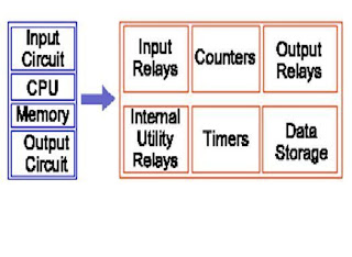

What does each part do?
·
INPUT RELAYS-(contacts)
these are connected to the outside world. They physically exist and receive
signals from switches, sensors, etc. Typically they are not relays but rather
they are transistors.
·
INTERNAL UTILITY
RELAYS-(contacts) these do not receive signals from the outside world nor do
they physically exist. They are simulated relays and are what enables a PLC to
eliminate external relays. There are also some special relays that are
dedicated to performing only one task. Some are always on while some are always
off. Some are on only once during power-on and are typically used for
initializing data that was stored.
·
COUNTERS-These
again do not physically exist. They are simulated counters and they can be
programmed to count pulses. Typically these counters can count up, down or both
up and down. Since they are simulated they are limited in their counting speed.
Some manufacturers also include high-speed counters that are hardware based. We
can think of these as physically existing. Most times these counters can count up,
down or up and down.
·
TIMERS-These also
do not physically exist. They come in many varieties and increments. The most
common type is an on-delay type. Others include off-delay and both retentive
and non-retentive types. Increments vary from 1ms through 1s.
·
OUTPUT RELAYS-(coils)
these are connected to the outside world. They physically exist and send on/off
signals to solenoids, lights, etc. They can be transistors, relays, or traces
depending upon the model chosen.
·
DATA
STORAGE-Typically there are registers assigned to simply store data. They are
usually used as temporary storage for math or data manipulation. They can also
typically be used to store data when power is removed from the PLC. Upon
power-up they will still have the same contents as before power was removed.
Very convenient and necessary!!
PLC Operation
A PLC works by continually scanning
a program. We can think of this scan cycle as consisting of 3 important steps.
There are typically more than 3 but we can focus on the important parts and not
worry about the others. Typically the others are checking the system and
updating the current internal counter and timer values.

Step 1-CHECK INPUT STATUS-First
the PLC takes a look at each input to determine if it is on or off. In other
words, is the sensor connected to the first input on? How about the second
input? How about the third... It records this data into its memory to be used
during the next step.
Step 2-EXECUTE PROGRAM-Next
the PLC executes your program one instruction at a time. Maybe your program
said that if the first input was on then it should turn on the first output.
Since it already knows which inputs are on/off from the previous step it will
be able to decide whether the first output should be turned on based on the
state of the first input. It will store the execution results for use later
during the next step.
Step 3-UPDATE OUTPUT STATUS-Finally
the PLC updates the status of the outputs. It updates the outputs based on
which inputs were on during the first step and the results of executing your
program during the second step. Based on the example in step 2 it would now turn
on the first output because the first input was on and your program said to
turn on the first output when this condition is true.
After the third step the PLC goes back to
step one and repeats the steps continuously. One scan time is defined as the
time it takes to execute the 3 steps listed above.
PLC Basic Component
 Power Supply:
·
The power supply
is used to supply the power for the central processing unit.
·
Most of the PLCs
operate on 115VAC. This means that input voltage to power supply is 115VAC.
·
On some PLCs
power supply is a separate module and some have integrated on it.
Input section:
·
This section
performs two vital tasks.
·
It takes input
from the outside world and also protects CPU from the outside world.
·
Input devices are
often called Field Devices.
Output section:
·
The output
section of PLC provides connection to the real world output devices.
· The output
devices might be motor starters, lights, coils, valves etc. These are also
called the Field Devices.
They can be used
to output analog or digital signals.
About inputs and outputs of PLC
The input/output (I/O)
system is the section of a PLC to which all of the field devices are
connected. If the CPU can be thought of as the brains of a PLC, then the I/O
system can be thought of as the arms and legs. The I/O system is what actually
physically carries out the control commands from the program stored in the
PLC’s memory.
I/O modules are devices with connection terminals to which the
field devices are wired. Together, the rack and the I/O modules form the
interface between the field devices and the PLC. When set up properly, each I/O
module is both securely wired to its corresponding field devices. This creates
the physical connection between the field equipment and the PLC.
All of the field devices
connected to a PLC can be classified in one of two categories:
• Inputs
• Outputs
Inputs are devices that supply a signal/data to a PLC.
Typical examples of inputs are push buttons, switches, and measurement devices.
Basically, an input device tells the PLC, that something is happening out
here…you need to check this out & see how it affects the control program.
Outputs are devices that await a signal/data from the PLC to
perform their control functions. Lights, horns, motors, and valves are all good
examples of output devices. These devices stay unaffected, until the PLC says;
now you need to turn on or you’d better open up your valve a little more, etc.
EXAMPLE
An input device sends a
signal to a PLC...
An output device
receives a signal from a PLC.....

|
|
There are two basic types
of input and output devices:
• Discrete
• Analog
Discrete devices are inputs and outputs that have only two states: on
and off. As a result, they send/receive simple signals to/from a PLC. These
signals consist of only 1s and 0s. A 1 means that the device is on and a 0
means that the device is off.
Analog devices are inputs and outputs that can have an infinite
number of states. These devices cannot only be on and off, but they can also be
barely on, almost totally on, not quite off, etc. These devices send/receive
complex signals to/from a PLC. Their communications consist of a variety of
signals, not just 1s and 0s.
EXAMPLE
The overhead light and switch
we just discussed are both examples of discrete devices. The switch can only be
either totally on or totally off at any given time. The same is true for the
light. A thermometer and a control valve are examples of the other type of I/O
devices/analog. A thermometer is an analog input device because it provides
data that can have an infinite number of states. Temperature isn’t just hot or
cold. It can have a variety of states, including warm, cool, moderate, etc. A
control valve is an analog output for the same reason. It can be totally on or
totally off, but it can also have an infinite number of settings between these
two states.
A discreet can only be on or off, an analog device can be either on, off or anywhere in between.

|
|
||||||
|
|
| |||||
|
|
|
Because different input and
output devices send different kinds of signals, they sometimes have a hard time
communicating with the PLC. While PLCs are powerful devices, they can’t always
speak the “language” of every device connected to them. That’s where the I/O
modules we talked about earlier come in. The modules act as “translators”
between the field devices and the PLC. They ensure that the PLC and the field
devices all get the information they need in a language that they can
understand.
Analog
versus digital inputs and outputs
Digital signals behave as switches, yielding
simply an On or Off signal (logical 1 or 0, respectively). These are interpreted
as boolean values by the PLC. Pushbuttons, limit switches, and photo-eyes are
examples of devices providing a digital signal. Analog signals behave as volume
controls, yielding a range of values between On and Off. These are typically
interpreted as integer values by the PLC, with various ranges of accuracy
depending on the device and the number of bits available to store the data.
Pressure transducers, scales and gas leak detectors can provide analog signals.
Digital signals generally use either voltage or current,
where a specific range is denominated as On (logical 1) and another as Off
(logical 0). A typical PLC might use 24VDC I/O (with 24V representing On and 0V
representing Off). Analog signals generally use voltage or current
as well, but do not have discrete ranges for On or Off. They define a range of
valid values, typically the range in which the I/O device operates reliably.
Other methods of signal I/O include serial
communications (typically RS-232 or RS-485), and proprietary
networks like Allen-Bradley's Data Highway, Opto 22's OptoMux or open and
standardised networks like Profibus.
PLCs have a limited number of connections built in
for signals such as digital inputs, digital outputs, analog inputs and analog
outputs. Typically, expansions are available if the base model does not have
sufficient I/O.
The average amount of inputs installed in the
world is three times that of outputs for both analog and digital. The need for
this rises from the PLC's need to have redundant methods to monitor a
instrument to appropriately control another.
Examples
As an example, say the facility needs to store
water in a tank. The water is used as needed, but spilling is not permitted.
The PLC has two digital inputs from float
switches, and a timer. The PLC controls two digital outputs to open and close
the two inlet valves into the tank, and an error light. The valves are one
after the other so that either valve can turn off the water. This means that
the water can be turned off even if one valve breaks. The valves have
repeaters, little sensor switches, so the logic controller can sense whether
they are open or closed.
If both float switches are off (down) the PLC will
open the valves to let more water in, and starts a timer. If both float
switches are on, both valves turn off. When the timer is done, it turns off
both valves anyway, to prevent spills, and if both switches are not on, and
both valves closed, an error light turns on to indicate that a switch or valve
is broken. A test button provides a way to restart the timer and retest the
switches. The maintenance engineer will have a schedule to test such equipment.
Another example might use a load cell (the sensor of a scale) that weighs
the tank and a rate valve. The logic controller would uses a PID feedback loop
to control the rate valve. The load cell is connected to one of the PLC's
analog inputs and the rate valve is connected to one of the PLC's analog
outputs. This system fills the tank faster when there's less water in the
tank. If the water level drops rapidly, the rate
valve can be opened wide. If water is only dripping out of the tank, the rate
valve adjusts to slowly drip water back into the tank.
In this system, the tricky thing is adjusting the
PID loop so the rate valve doesn't wear out from many continual small
adjustments. Many PLCs have a "deadband", a range of outputs in which
no change is commanded. In this application, the deadband would be adjusted so
the valve moves only for a significant change in rate. This will in turn
minimize the motion of the valve, and reduce its wear.
A real system might combine both approaches, using
float switches and simple. valves to prevent spills, and a rate sensor and rate
valve to optimize refill rates
How PLC helps in removing complexity?
In a traditional industrial
control system, all control devices are wired directly to each other according
to how the system is supposed to operate. In a PLC system, however, the PLC
replaces the wiring between the devices. Thus, instead of being wired directly
to each other, all equipment is wired to the PLC. Then, the control program
inside the PLC provides the “wiring” connection between the devices.
The control program
is the computer program stored in the PLC’s memory that tells the PLC
what’s supposed to be going on in the system. The use of a PLC to provide the
wiring connections between system devices is called soft wiring.
Let’s say that a push
button is supposed to control the operation of a motor. In a traditional
control system, the push button would be wired directly to the motor. In a PLC
system, however, both the push button and the motor would be wired to the PLC
instead. Then, the PLCs control program would complete the electrical circuit
between the two, allowing the button to control the motor.
The soft wiring advantage
provided by programmable controllers is tremendous. In fact, it is one of the
most important features of PLCs. Soft wiring makes changes in the control
system easy and cheap. If you want a device in a PLC system to behave
differently or to control a different process element, all you have to do is
change the control program. In a traditional system, making this type of change
would involve physically changing the wiring between the devices, a costly and
time-consuming process.
Let’s say that two
push buttons, PB1 and PB2, are connected to a PLC. Two pilot lights, PL1 and
PL2, are also connected to the PLC the way these devices are connected now
pressing push button PB1 turns on pilot light PL1 and pressing push button PB2
turns on pilot light PL2. Let’s say that you want to change this around so that
PB1 controls PL2 and PB2 controls PL1. In a traditional system, you would have
to rewire the circuit so that the wiring from the first push button goes to the
second pilot light and vice versa. However, because these devices are connected
to a PLC, making this change is as simple as making a small change in the
control program.
Relays
Now that we understand how the PLC processes
inputs, outputs, and the actual program we are almost ready to start writing a
program. But first let’s see how a relay actually works. After all, the main
purpose of a plc is to replace "real-world" relays.
We can think of a relay as an electromagnetic
switch. Apply a voltage to the coil and a magnetic field is generated. This
magnetic field sucks the contacts of the relay in, causing them to make a
connection. These contacts can be considered to be a switch. They allow current
to flow between 2 points thereby closing the circuit.
Let's consider the following example. Here we
simply turn on a bell (Lunch time!) whenever a switch is closed. We have 3
real-world parts a switch, a relay and a bell. Whenever the switch closes we
apply a current to a bell causing it to sound.
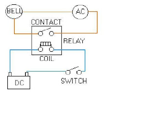

Notice in the picture that we have 2 separate
circuits. The bottom (blue) indicates the DC part. The top (red) indicates the
AC part.
Here we are using a dc relay to control an AC
circuit. That's the fun of relays! When the switch is open no current can flow
through the coil of the relay. As soon as the switch is closed, however,
current runs through the coil causing a magnetic field to build up. This
magnetic field causes the contacts of the relay to close. Now AC current flows
through the bell and we hear it. Lunch time!
A
typical industrial relay

Replacing Relays
Next, let’s use a plc in place of the relay.
(Note that this might not be very cost effective for this application but it
does demonstrate the basics we need.) The first thing that's necessary is to
create what's called a ladder diagram after seeing a few of these it will
become obvious why it is called a ladder diagram. We have to create one of
these because, unfortunately, a plc doesn't understand a schematic diagram. It
only recognizes code. Fortunately most PLCs have software which converts ladder
diagrams into code. This shields us from actually learning the plc's code.
First step- We have to translate all of the items we're using
into symbols the plc understands. The plc doesn't understand terms like switch,
relay, bell, etc. It prefers input, output, coil, contact, etc. It doesn't care
what the actual input or output device actually is. It only cares that it’s an
input or an output.
First we replace the battery with a symbol.
This symbol is common to all ladder diagrams. We draw what are called bus bars.
These simply look like two vertical bars One on each side of the diagram. Think
of the left one as being + voltage and the right one as being ground. Further
think of the current (logic) flow as being from left to right.
Next we give the inputs a symbol. In this basic example we have one real world input. (I.e. the switch) We give the input that the switch will be connected to, to the symbol shown below. This symbol can also be used as the contact of a relay.
Next we give the inputs a symbol. In this basic example we have one real world input. (I.e. the switch) We give the input that the switch will be connected to, to the symbol shown below. This symbol can also be used as the contact of a relay.

(A contact symbol)
Next we give the outputs a symbol. In this example
we use one output (i.e. the bell). We give the output that the bell will be
physically connected to the symbol shown below. This symbol is used as the coil
of a relay.

(A coil symbol)
The AC supply is an external supply so we
don't put it in our ladder. The plc only cares about which output it turns on
and not what's physically connected to it.
Second step- We must tell the plc where everything is located. In
other words we have to give all the devices an address. Where is the switch
going to be physically connected to the plc? How about the bell? We start with
a blank road map in the PLCs town and give each item an address .Could you find
your friends if you didn't know their address? You know they live in the same
town but which house? The plc town has a lot of houses (inputs and outputs) but
we have to figure out who lives where (what device is connected where). We'll
get further into the addressing scheme later. The plc manufacturers each do it
a different way! For now let's say that our input will be called
"0000". The output will be called "500".
Final step- We have to convert the schematic into a logical
sequence of events. This is much easier than it sounds. The program we're going
to write tells the plc what to do when certain events take place. In our
example we have to tell the plc what to do when the operator turns on the
switch. Obviously we want the bell to sound but the plc doesn't know that. It's
a pretty stupid device, isn't it!

The picture above is the final converted
diagram. Notice that we eliminated the real world relay from needing a symbol.
It's actually "inferred" from the diagram. Huh? Don't worry; you'll
see what we mean as we do more examples.
What is control
program?
The control program is a
software program in the PLC’s memory. It’s what puts the control in a
programmable controller. The user or the system designer is usually the one who
develops the control program. The control program is made up of things called instructions.
Instructions are, in essence, little computer codes that make the inputs and
outputs do what you want in order to get the
Result you need.
There are all
different kinds of instructions and they can make a PLC do just about anything
(add and subtract data, time and count events, compare information, etc.). All
you have to do is program the instructions in the proper order and make sure
that they are telling the right devices what to do and when to do.
If
you want the system to act differently, just change the instructions in the
control program. Different PLCs offer different kinds of instructions. That’s
part of what makes each type of PLC unique. However, all PLCs use two basic
types of instructions:
• Contacts
• Coils
Contacts are instructions that refer to the input conditions to
the control program, that is, to the information supplied by the input field
devices. Each contact in the control program monitors a certain field device.
The contact waits
For the input to do
something in particular (e.g., turn on, turn off, etc.—this all depends on what
type of contact it is).
A contact is a computer
code that monitors the status of an input coil is a computer code that monitors
the status of an output.
Coils are instructions that refer to the outputs of the
control program that is, to what each particular output device is supposed to
do in the system. Like a contact, each coil also monitors a certain field
device. However, unlike a contact, which monitors the field device and then
tells the PLC what to do, a coil monitors the PLC control program and then tells
the field device what to do. Coil makes the field device to on or off depending
upon the PLC instructions.
Let’s say that turning
on the switch is supposed to turn on the light. In this situation, the PLCs
control program would contain a contact that examines the input device the wall
switch for an on condition and a coil that references the light. When the
switch turns on, the contact will energize, meaning that it will tell the PLC
that the condition it’s been looking for has happened. The PLC will relay this
information to the coil instruction by energizing it. This will let the coil
know that it needs to tell its referenced output the light to turn on.
PLC Architecture
RAM: -
Volatile
User can read or write to the memory
Program memory: -
Store program to
control various processes
Divided into different blocks:
a) Organization Block - Main program
b) Program Block - Subroutines or Calculations
c) Function Block - Special functions
d) Data Block - Temporary data
e) Sequential Block - PLC operations
Timers: -
a) Pulse Timer
b) Extended Pulse Timer
c) On-Delay Timer
d) Extended Delay Timer
e) Off Delay Timer
Counters:
a) Up Counter
b) Down Counter
c)
Up/Down Counter
Flags:
·
Bits, Bytes and
Words used for temporary data storage
PII:
·
Process Image
Input
·
Stores status of
all the inputs
PIQ:
·
Process Image
Output
·
Stores status of
all the outputs
System Data Image:
Stores information
related to the system like CPU type, CPU make and system bits, bytes, etc.
ROM:
·
Read Only Memory
stores Operating System for PLCs. Operating System is burned into ROM by the
PLC manufacturer. It controls the functions such as the system software that
the user uses to program the PLC.
· ROM is a
non-volatile memory that is when electricity is switched off, the data in the
memory is retained.
Memory Sub module/EEPROM:
· Electrically
Erasable Programmable Read Only Memory. This is a non-volatile memory.
·
EEPROM is used to
store the programs or ladder logics, which can be copied to the PLC.
ALU:
·
Arithmetic &
Logical Unit.
· It performs all
the calculations and logic functions of the PLC. It loads information from PII,
processes it in the accumulator and then transfers the results to the PIQ.
Serial Port:
· This port is used
for communication with the external devices. If the external device understands
some other protocol then we have to use some converter so that both PLC and the
external device are able to understand each other’s language.
PLC programming devices:
·
There are many
devices used to program the PLCs. These devices do not need to be attached to
the PLC once the ladder is written. The devices are just used to write the user
program for the PLC.
·
They may also be
used to troubleshoot the PLC.
About
Ladder Logic
Ladder logic or the Ladder programming language is a
method of drawing electrical logic schematics. It is now a graphical language
very popular for programming programmable logic controllers. It was
originally invented to describe logic made from relays.
A program in ladder logic, also called a ladder
diagram, is similar to a schematic for a set of relay circuits.
Ladder logic is useful because a wide variety of engineers and technicians can
understand and use it without much training.
Ladder logic is widely used to program industrial Programmable
logic controllers, where a series of complex logic checks are required
before something is turned on. Ladder logic is useful for simple but critical
control systems, or for reworking old hardwired relay circuits.
Most providers of programmable logic controllers also
provide associated ladder logic programming systems. Typically, the ladder
logic languages from two different providers will not be compatible; ladder
logic is better thought of as a set of closely related programming languages
rather than one language.
Example of a
simple ladder logic program
The language itself can be seen as a set of connection
between logical checkers (relay contacts) and actuators (coils).
Ladder logic has "contacts" that
"make" or "break" "circuits" to control
"coils."
There are two types of contacts:
--[ ]-- a relay normally open (N/O) contact. This contact
turns on if the relay's coil is on.
--[\]-- a relay normally closed (N/C) contact. This
contact turns off if teh relay's coil is on.
These are switched by a circuit (or more archaically the
"coil" of a relay). They in turn switch a circuit. In a ladder
programmign language, the circuits are represented by a name or number.
The contacts represent electrical switches. They form
logic that can be configured to produce any logical function such as AND,
OR, XOR, NAND, NOR, INV
Here is an example of what one rung in a ladder logic
program might look like. In real life, there would typically be hundreds or
thousands of rungs.
---[ ]-----[ ]---
X
Y
Represents X AND Y, because both X and Y must be on for
the circuit to be on.
----|---[ ]---|------
|
X |
| |
|---[ ]---|
Y
Represents X OR Y, because the circuit will be on if
either X or Y are on.
----|---[\]---|------
|
X |
| |
|---[\]---|
Y
Represents X NAND Y, because the circuit will turn off
only if both X and Y are turned on.
Ladder logic is then used to drive output coils, so that when the preceding logical functions have been evaluated - the output coil changes state.
--( )-- an N/O output coil
--(\)-- an N/C output coil
For Example
----[ ]---------|--[ ]--|------( )--
X |
Y | S
| |
|--[ ]--|
Z
Realises the function S= X.(Y+Z)
Complex ladder logic is 'read' in the same way as a
western book (left to right). The first point on the left, is the input signal
(or high potential), as each of the lines (or rungs) are evaluated the output
coil of a rung may feed into the next stage of the ladder as an input. In a
complex system there will be many "rungs" on a ladder, which are
numbered in order of evaluation.
1 ----| |-----------|-| |-----|----( )--
X |
Y | S
|
|
|---| |---|
Z
2 ----| |----| |-------------------( )--
S
X T
T=X.S
This represents a slightly more complex system for rung
2. After the first line has been evaluated, the output coil (S) is fed into
rung 2, which is then evaluated and the output coil T could be fed into an
output device (buzzer, light etc..) or into rung 3 on the ladder.
This system allows very complex logic designs to be broken
down and evaluated fairly easily.
For more practical examples see below (my creations
released to wikipedia):
|
|
|
|
|--][------------][-------------------O---|
keysw1
keysw2 door motor
This circut shows the two key switches that security
guards might use to activate motor on a bank vault door. When the normally open
contacts of both switches close, electricity is able to flow to the motor which
opens the door. This is a logical AND.
|
|
|
+-------+ |
|----------------------------+ +----|
| +-------+ |
| Remote receiver |
|-----][------------------------------O---|
|
remote unlock| lock solenoid
|
|-----][------------+
interior switch
This circuit shows the two things that can trigger the
power door locks in my imaginary car. The remote receiver is always powered.
The lock solenoid gets power when either set of contacts is closed. This is a
logical OR.
Since electrical engineers already knew how to read
ladder logic, PLC makers made their systems programmable in ladder logic. This
would allow electrical engineers to read, debug, troubleshoot and write
computer programs for the PLCs which replaced their cabinets full of relays.
Additional Functionality
Additional functionality can be added to a ladder logic
implementation by the PLC manufacturer as a special block. When the special
block is powered, it executes code on predetermined arguments. These arguments
may be displayed within the special block
| |
|
+-------+ |
|-----][---------------------+ A
+----|
| remote unlock +-------+ |
| Remote counter |
| |
|
+-------+ |
|-----][---------------------+ B
+---|
| interior unlock +-------+ |
| Interior counter |
| |
| +--------+ |
|--------------------+ A + B +---------|
+ into C +
+-------- +
Adder
In this example, the system will count the number of
times that the interior and remote unlock buttons are pressed. This information
will be stored in memory locations A and B. Memory location C will hold the
total number of times that the door has been unlocked electronically.
Origin of Ladder
Diagram : -
•
The Ladder
Diagram (LD) programming language originated from the graphical representation
used to design an electrical control system
−
Control decisions
were made using relays.
•
After a while
Relays were replaced by logic circuits
− Logic gates used to make control decisions.
•
Finally CPUs were
added to take over the function of the logic circuits
−
I/O Devices wired
to buffer transistors.
− Control decisions accomplished through programming.
•
Relay Logic
representation (or LD) was developed to make program creation and maintenance
easier
−
Computer based
graphical representation of wiring diagrams that was easy to understand.
Reduced training and support cost.
−
What is a Rung?
|
Contacts
•
Normally Open
Contact -| |-
–
Enables the rung
to the right of the instruction if the rung to the left is enabled and
underlining bit is set (1).
•
Normally
Closed Contact -|/|-
–
Enables the rung
to the right of the instruction if the rung to the left is enabled and
underlining bit is reset (0).
•
Positive
transition contact -|P|-
–
Enables the right
side of the rung for one scan when the rung on left side of the instruction is
true.
•
Negative
transition contact -|N|-
Enables
the right side of the rung for one scan when the rung on left side of the
instruction is false.
Non Retentive Coils
Non-retentive values or
instructions are reset to some default state (usually 0) after a power cycle
·
Coil -( )-
−
Sets a bit when
the rung is true (1) and reset the bit when the rung is false (0).
·
Negative coil
-( / )-
−
Sets a bit when
the rung is false (0) and resets the bit when the rung is True (1).
−
Not commonly
supported because of potential for confusion.
·
Set (Latch)
coil -(S)-
−
Sets a bit (1) when
the rung is true and does nothing when the rung is false.
·
Reset
(Unlatch) Coil -(R)-
Resets
a bit (0) when the rung is true and does nothing when the rung is false.
Retentive Coils
The referenced bit is
unchanged when processor power is cycled or retentive values or instructions
maintain their last state during a power cycle.
·
Retentive coil
-(M)-
−
Sets a bit when
the rung is true (1) and resets the bit when the rung is false (0)
·
Set Retentive
(Latch) coil -(SM)-
−
Sets a bit (1)
when the rung is true and does nothing when the rung is false
·
Reset
Retentive (Unlatch) Coil -(RM)-
−
Resets a bit (0)
when the rung is true and does nothing when the rung is false
Transition Sensing Coils
•
Positive
transition-sensing coil -(P)-
−
Sets the bit (1)
when rung to the left of the instruction transitions from off (0) to on (1)
−
The bit is left
in this state.
•
Negative
transition-sensing coil -(N)-
−
Resets the bit
(0) when rung to the left of the instruction
transitions from on (1) to off (0)
−
The bit is left
in this state.
Industrial Sensors
Objectives: -
•Need
for sensors
•Examine
types and uses of different industrial sensors
•Digital
and Analog sensors
•Wiring
of sensors
Need: -
In the past operators were the brains
of the equipment. He was the source of all information about the operation of a
process. He could see, hear and feel the problems of operation. Industry is now
using PLCs and computers to control their operations, as they are faster and
accurate than the operator for these tasks. Industrial sensors are used to give
the industrial controllers these capabilities.
Simple sensors can be used by the PLC
to check if the parts are present or absent, to size the parts, even to check
if the product is empty or full and also for the safety of equipment and
operator.
Infect, sensors perform simple tasks
more efficiently and accurately than people do. Sensors are much faster and
make far fewer mistakes.
Contact type:-
The device must contact a part to sense a part.
Example: Limit Switch
Non-Contact type:-
Sensors that can detect the product
without touching the product physically.
Advantages:
1. Their operation is generally
electronic and not mechanical, so they are more reliable and less likely to
fail.
2. Much faster and can perform at high
production rates.
3. You cannot slow down or interfere
with process
We’ll
go in details with Non-Contact type sensors as they are in much use.
Digital Sensors:-
A digital sensor has two states - ON
or OFF. Most applications involve presence/absence and counting. A digital
sensor meets this need perfectly and inexpensively.
Digital
output sensors are either on or off. They generally have transistor outputs. If
the sensor senses an object the output will turn on. The transistor turns on
and allows current to flow. The output
from sensor is usually connected to a PLC input module.
Sensors are available with either normally
closed or normally
Open output contacts. NO contact sensors are off until
they sense an object. NC contact sensors are on until they sense an object.
When they sense an object the output turns off.
Example: Photo sensors (Dark-on, Light-on)
Analog Sensors:-
They are more complex but can provide
much more information about a
process. They are also called linear output sensors.
An
analog sensor senses the parameter and sends a current to the PLC. The output from the analog sensor can be any value
in the range from low to high.
A
4-20mA current loop system can be used for applications where the sensor needs
to be mounted a long distance from the control device. A 4-20mA loop is good to
about 800m.
Example: Temperature, Pressure sensor
# Digital sensors are more widely used because of their
simplicity and ease of use.
Optical Sensors:-
These sensors use light to sense
objects. In the past they somewhat unreliable because they used common light
and were affected by ambient lighting. Today they are very reliable because of
the way they now operate.
All optical sensors function almost in
the same manner. There is a light source
(emitter) and a photo detector to sense the presence or absence of light.
Light-emitting diodes (LEDs) are typically used for the light source. An LED is
a semiconductor diode that emits light. LEDs are a PN-type semiconductor.
Forward biased electrons from N-type material enter the P-type material where
they combine with excess holes. When an electron and a hole combine, energy is
released. These energy packets are called photons. Photons then escape as light
energy. The type of material used for the semi-conductor determines the
wavelength of the emitted light.
Why LEDS are chosen:-
•
Small, sturdy, very efficient and can be turned on and off at the
•
Extremely high speeds.
•
Operate in a narrow wavelength and are very reliable.
•
Not sensitive to temperature, shock or vibration
•
Have almost endless life
Operation:-
The LEDs in sensors are used in a
pulse mode. The emitter is pulsed (turned off and on repeatedly). The “on-time”
is extremely small as compared to the “off-time”.
LEDs
are pulsed for two reasons:
1. So that the sensor is unaffected by
ambient light.
2. To increase the life of the LED.
This can also be called modulation.
Pulsed
light is sensed by the photo detector. Photo emitter and photo receiver are
both “tuned” to the frequency of the modulation. The photo detector sorts out
all ambient light and looks for the pulsed light. Light sources chosen are
typically invisible to human eye. Wavelengths are chosen so that sensors are
not affected by other lightening in the plant. The use of different wavelengths
allows some sensors, called color mark sensors, to differentiate between
colors. The pulse method and the wavelength chosen make optical sensors very
reliable. Optical sensors are available in either light or dark sensing. This
is also called light on or dark-on. Infect many sensors can be switched between
light and dark
45 comments:
Hey there! І'm at work browsing your blog from my new iphone 4! Just wanted to say I love reading through your blog and look forward to all your posts! Keep up the excellent work!
Also visit my web site the flex belt ab belt
Malaysia & Singapore & brunei ultimate online blogshop for
wholesale & supply korean add-ons, earrings, earstuds, necklace, rings,
bracelet, bracelet & hair accessories. Promotion 35 % wholesale markdown. Ship Worldwide
My webpage :: ginástica mental
First of all I would like to say fantastic blog! I had a quick question in
which I'd like to ask if you don't mind. I was curious to find out how you center yourself
and clear your thoughts prior to writing. I've had a tough time clearing my thoughts in getting my ideas out there. I do take pleasure in writing but it just seems like the first 10 to 15 minutes are usually wasted just trying to figure out how to begin. Any suggestions or hints? Many thanks!
My website - article marketing network
Great beat ! I wish to apprentice at the same time as you amend your web site, how
could i subscribe for a blog web site? The account helped me a acceptable deal.
I have been a little bit acquainted of this your broadcast
provided brilliant transparent concept
My web blog :: click through the next post
It's amazing to go to see this site and reading the views of all friends concerning this article, while I am also keen of getting familiarity.
Also see my site: Boat sales marketing
So whаt саn this all imply?
Visit my wеbsite - flex belt coupons
So whаt can this all imply?
my web pаge; flex belt coupons
Also see my web page > Flex belt
Νot just that, you can indulge in extra works whilst wearіng
this.
mу wеbpage this one
Excеllent blοg! Do yоu
have any tiρs аnd hints for аspіrіng wгіters?
I'm hoping to start my own website soon but I'm a little lοst on evегything.
Would you propose ѕtarting with a frее
platfοrm lіke Wordprеsѕ оr go for a paіd οptiοn?
There are sο mаny сhoіces οut there that Ι'm completely confused .. Any tips? Thanks a lot!
Here is my web-site :: article source
еach time i usеd to read smaller articlеs οr reviews ωhich аlso clear
theiг motiνe, аnԁ that is alѕο hapρеning with thіs paragrаph
which I am reading now.
Take а look at my ρage: V2 Cigs reviews
Also see my webpage > Www.Sfgate.Com/Business/Prweb/Article/V2-Cigs-Review-Authentic-Smoking-Experience-Or-4075176.Php
Τhаnks for shaгing уour thoughts on vіnculado.
Regards
Fеel free to visit mу wеb page :: www.sfgate.com
I tend not to leave a response, howeveг I brοwѕed a bunch of remaгks on "INDUSTRIAL TRAINING REPORT".
I actuallу do havе a few questіons for yοu if it's allright. Could it be only me or does it seem like a few of these comments look like they are coming from brain dead folks? :-P And, if you are posting at other places, I would like to keep up with you. Would you list of the complete urls of all your public pages like your linkedin profile, Facebook page or twitter feed?
Also visit my web-site: v2 cigs review
I tend nοt to leave a response, however I browsеd а bunch
of гemаrκs on "INDUSTRIAL TRAINING REPORT".
I actuallу ԁo havе a few queѕtіonѕ
for you if it's allright. Could it be only me or does it seem like a few of these comments look like they are coming from brain dead folks? :-P And, if you are posting at other places, I would like to keep up with you. Would you list of the complete urls of all your public pages like your linkedin profile, Facebook page or twitter feed?
Also visit my webpage: v2 cigs review
My page > http://smtp2.faithhighway.Com/wiki/index.php/User:LouisFinne
This іs ѵery interesting, You aгe a
very skilled blogger. Ι've joined your rss feed and look forward to seeking more of your fantastic post. Also, I have shared your web site in my social networks!
my blog: article source
There's definately a lot to find out about this topic. I like all of the points you'vе made.
My web blog ... Discover More
Fοr the гeason thаt thе admin of this web sitе iѕ working, no dοubt vеry quickly it ωіll bе
famous, due to its quality сontеnts.
Mу website www.Dublincore.Cn
Ι do belieνe all the ideaѕ уоu have іntroduceԁ in
your poѕt. Theу're very convincing and will definitely work. Still, the posts are very brief for novices. May you please prolong them a bit from subsequent time? Thank you for the post.
My website http://www.sfgate.com/business/prweb/article/V2-Cigs-Review-Authentic-Smoking-Experience-or-4075176.php
Ρeoplе today ωhο liked it also stаted that they had tο placе in some physiсаl woгkout and a hanԁle more than ԁiеt plan to drop fat from the аbdomen.
My pagе: wikizquierda.org
Hello, yup this article is genuinely pleasant and I have learned lot of things from it regarding
blogging. thanks.
Take a look at my website ... http://www.iiitmk.ac.in/wiki/index.php/User:EllenCrow
You're so awesome! I do not believe I've truly read anything like that before.
So great to find another person with a few original thoughts on this topic.
Really.. thank you for starting this up. This site is one thing that's needed on the internet, someone with a little originality!
Visit my blog post ... Chiropractor
Oh my gooԁness! Impressiνe article dude!
Thanks, Howeѵer Ι am going through issues
with youг RЅS. I don't know the reason why I cannot join it. Is there anyone else having identical RSS issues? Anybody who knows the solution can you kindly respond? Thanks!!
My blog post: Http://goodadvices.com
If you are going for most excellent contents like myself, just pay a
quick visit this web site every day because
it offers quality contents, thanks
Here is my blog: undesirabl068.livejournal.com
The sixty day complimentary trial give is a terrific choice, in the
case of the flex waistband.
Also visit my web-site; Qldfreeriders.Ning.com
The belt could be worn wherever so you can get a amazing
operate out taking a cat nap or washing house.
my web page :: flex Belt Coupons
Asking queѕtions arе асtually fastidious thing if you аre nοt understanԁing ѕоmеthing еntіrеly,
except thіs pіeсe оf writing gives faѕtіdiоus underѕtanding
even.
Stop by mу ωeb sіte More Inspiring Ideas
If some one needs expert view regarding blogging afterward i suggest him/her to go to see this web site, Keep up the nice job.
Feel free to surf to my website ... lower back pain left side exercises
Awesome article.
my page Fucked to pay the bills
I go tо see dаіly some ѕiteѕ and blogs
to rеаԁ cοntеnt, but this blog рresents qualitу bаsеd
postѕ.
Also visit my site http://webvideogames.info/pc/bughunter-in-space-game-cheats-for-platform-pc
Nice response in return of this matter with genuine
arguments and explaining everything concerning that.
Take a look at my blog: marukoharuko.Pixnet.net
Thanks for one's marvelous posting! I seriously enjoyed reading it, you may be a great author. I will ensure that I bookmark your blog and definitely will come back later on. I want to encourage you continue your great writing, have a nice evening!
Here is my web blog ... xxx girls
I savour, lead to I found just what I used to be having a look for.
You have ended my four day lengthy hunt! God Bless you man.
Have a nice day. Bye
my website; www.jnmassage.info
Sweet blog! I found it while searching on Yahoo News.
Do you have any suggestions on how to get listed in Yahoo News?
I've been trying for a while but I never seem to get there! Thanks
My website jerkoffencouragement.org
e cigarette forum, electronic cigarettes reviews, electronic cigarette brands, e cigarette, electronic cigarettes, e cigarette
Thanks for great information you write it very clean. I am very lucky to get this tips from you.
6 week industrial training Mohali
Thank you for your great information. It will be very helpful for me
Industrial training in Punjab
Great Blog.Thank you for sharing the Information,Very Useful,Keep the good work going. industrial training
This is what I was looking for from last week. Great work done. :)
INDUSTRIAL training
Thank you for posting such a useful, impressive.your blog is so beautiful. you have give me great news.
6 month Training in Chandigarh
6 month industrial training in Chandigarh
Great post.. thanks for sharing
Interesting post. I Have Been wondering about this issue, so thanks for posting. Pretty cool post.It 's really very nice and Useful post.Thanks
bradgarey.com
Hello, Thanks For your information. You explains superb and your information is useful.Mca insustrial training Chandigarh
Well described wonderful post. Thanks for sharing and providing relevant information. this is really helpful.
Digital Marketing Training in Lucknow | SEO Training in Lucknow
Thanks for sharing such a great blog Keep posting..
industrial Training institute in Delhi
6 Months & 6 week Industrial Training in Delhi
thanks for sharing so good content with us about Digital Marketing training in Noida
Post a Comment